|
||||||||
|
Tinkering |
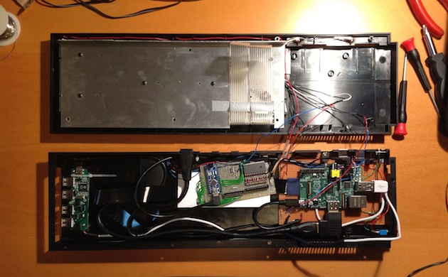
QL Keys, part 2Integrating a Raspberry PiIn the previous article a Sinclair QL has been converted to a USB keyboard. The next step is cramming in a Raspberry Pi. One of the reasons to put the Raspberry Pi in a larger enclosure is the fact that the ports on the device are situated on all of its four sides. The resulting cable explosion can be tamed somewhat by routing all the connectors to one side, following the example of an eighties home-computer style case. (The other reason is that the QL case looks totally cool.) The image above shows the result of a decent number of evenings spent on this project. The whole can now function in two modes:
Explanations of the modifications and additions are given below.
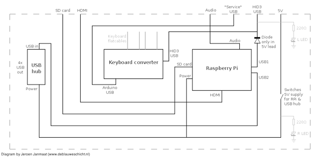
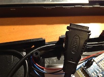
Keyboard matrix to USB converterThis circuit is discussed in the previous article, but the Arduino Uno in the original setup has been replaced by an Arduino Nano to reduce the size to a single board. Both the added USB port and the primary USB port on the Arduino itself are routed to the rear of the QL case. The first to connect the converter to a host PC (to allow use as a HID class device) and the second to allow reprogramming the Arduino in situ if necessary. HDMI portHDMI is exported using a 90 degree angled adapter and a short (50 cm) cable. The female connector of the latter has been modified to fit in one of the original controller cavities; I simply filed slots in the plastic casing of the connector and could make it fit quite snugly, with no need for glueing or other fastening aid. Slight local modification of the upper edge of the bottom half of the QL case was necessary here.
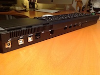
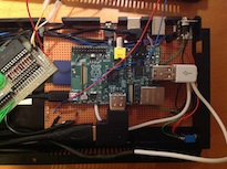
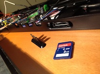
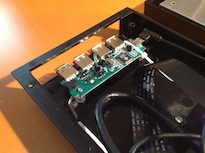
SD cardThe ROM port on the back side of the historical QL now holds the SD card slot. This is achieved using an SD card extender. The original blind can still be fitted. USB portsThe first generation RPi model B used here features two USB ports. One of these is connected to the keyboard converter (powering it also) and the other is connected to a USB hub. Connections to these ports are made using two modified inexpensive iPhone/iPad USB cables (on account of their thin and flexible leads). In both modes of operation (as a HID device for an external computer and as a Raspberry Pi machine) the keyboard converter is powered through the 5V pin on the Arduino. In order to prevent powering the RPi through the Arduino when connected to a computer, a diode has been placed in the +5V lead of the keyboard connection coming from the RPi. This may qualify as a somewhat dirty hack as it lowers the supply voltage of the Arduino when the RPi is in use, but but the 0.7V drop caused by the diode in this mode does not seem to hamper the operation of the Arduino. The four-port USB hub is placed near the expansion port on the left side of the historical QL. The original door can still be fitted if no peripherals are connected to the hub. The version of the RPi used here can only provide limited output current on its USB ports; for this reason, it is necessary to power the USB hub externally. Newer RPi's have been improved in this respect, so that this may be unnecessary for those boards.
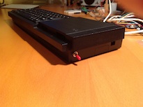
AudioVery simple; just a short extension lead with a PCB-mounted jack soldered on. LightsThe two LEDs on the right side of the machine that originally indicated microdrive activity are now wired to indicate which subsystems are powered; RPi and Arduino or Arduino only (the original power LED on the left side now functions as a Caps Lock indicator). Power switchUnlike the original Sinclair QL (and the RPi), this machine has an on/off switch! It switches the +5V from an external power source to both the RPi and the USB hub. It should be switched off if connected to a host computer. Final notesSome ports are presently not featured externally, notably analog video out (as I only use the digital output), the I/O headers, and the RJ-45 network connector (a Wi-Fi dongle is used on the USB hub). Most parts have been bought on ebay. The SD card extender, the USB hub, USB cables, the HDMI cable and 90 degree adapter, and the Wi-Fi dongle can all be had for reasonable prices from various vendors. Loose ends:
(Originally written 2012/12/16)
|
