|
|||||||||||||||||||||||
|
Tinkering |
Using the MOS 6581 SID chip (part 1)Much has been - and is still being - said and written about MOS Technology's SID chip. SID stands for "Sound Interface Device"; it was designed by Robert Yannes in 1981 and subsequently used as the sound source in the enormously successful Commodore 64 home computer. In present times the SID is still used for its distinctive sound, both in its original environment (i.e. the C64) and in newer applications. In my collection of old computers there is a defective C64; I salvaged the 6581 SID that lay dormant therein to learn more about this legendary device and how to interact with it. ExtractionStep one is to remove the SID chip from the C64. This is a tricky job; the 28-pin DIL package is soldered directly onto the main board and it requires care and patience to liberate the SID without damaging it. This YouTube video offers helpful information for getting this done (apparently desoldering components from old PCB's can be made a lot easier by first resoldering the pins with new solder). Incidentally, SID chips can also be found on on-line auction sites like ebay (but beware, rumor has it that there are defective and non-functional counterfeit ones on the market advertised as the real thing).
AnatomyNow that the chip is removed, it is time to investigate its anatomy. The folks at 6502.org have made available a PDF of the (preliminary) version of the datasheet. This document provides the necessary information to operate the SID, including pinout, register description and an example application schematic.
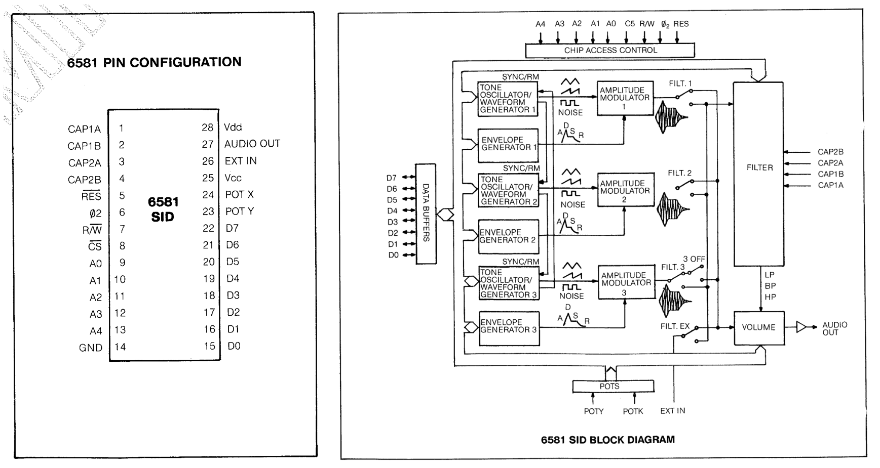
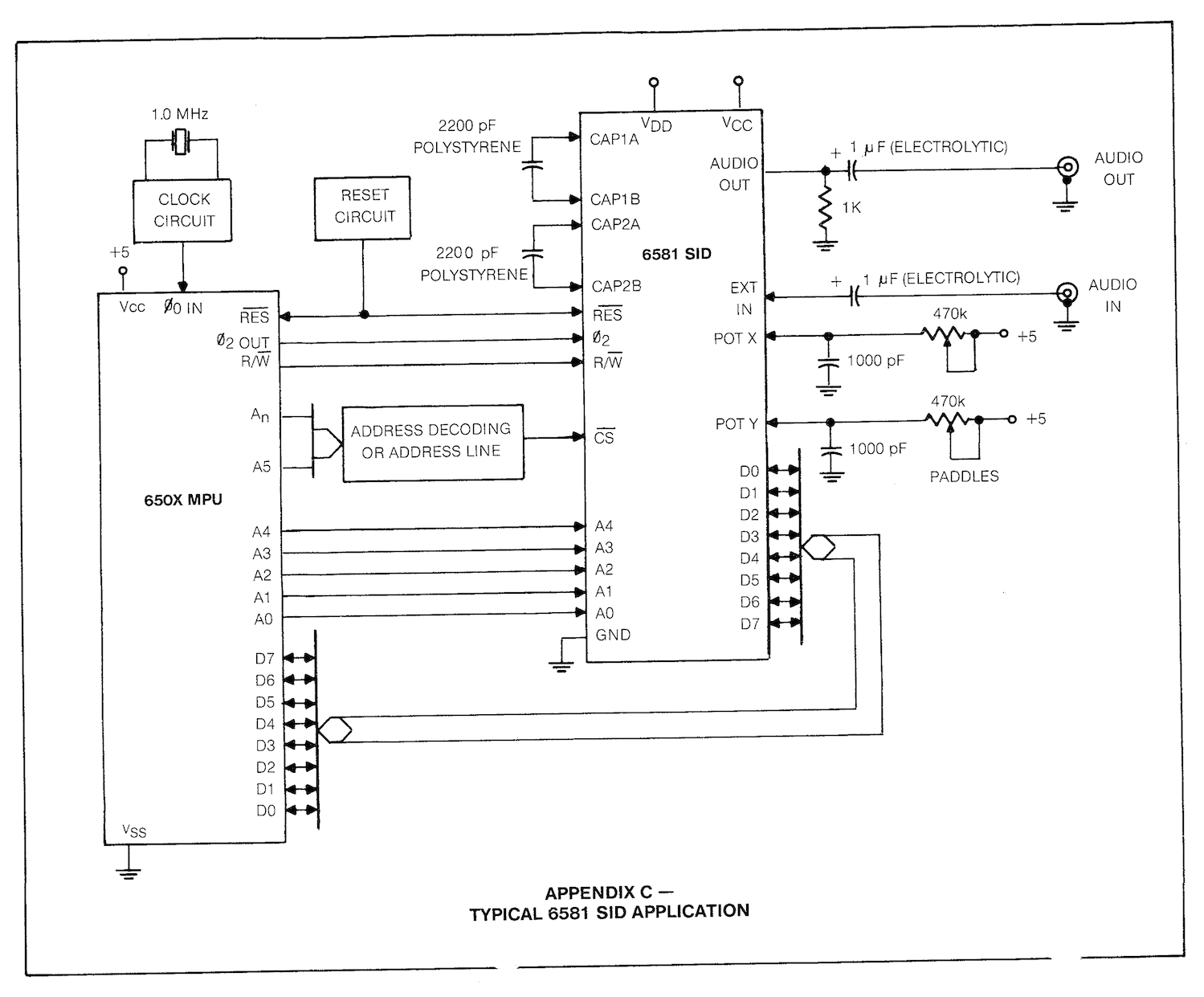
From a programmer's perspective, the SID consists of a number of registers that control three voices. Each voice can be set to a frequency, a volume envelope and a waveform (and pulse width when applicable). A further register controls volume and filter characteristics, and acts on all three voices at once. These are all write-only registers; there are also a number of read-only addresses that return values for two potentiometers (if attached) after digitization and data derived from voice 3 that can be used for modulation effects. The pinout shows an address bus and a data bus (A0-A4 and D0-D7, respectively), through which the SID's registers are selected and programmed. These are augmented by various controls, namely Reset, Read/Write Select, and Chip Select. Further important connections are Phi2 for the 1 MHz clock signal, the Audio Out pin and the Vdd and Vcc supply voltage pins. For the operation of the built-in filter two capacitors are to be connected as well. Lastly, it is possible to connect an input signal and up to two potentiometers can be attached to the built-in 8-bit AD converters. It is important to note that there have been a number of incarnations of the SID. The one under scrutiny here is the MOS 6581, with a Vdd of 12V. A later version, the 8580, is an improvement in various ways, and requires a Vdd of 9V. Vcc is the familiar TTL-level voltage of 5V. Reviving SIDMotivating the SID to produce sound involves two distinct tasks: first to provide the necessary electrical environment for the chip to work and second to properly program the registers mentioned earlier. Appendix C in the datasheet provides a schematic that illustrates how to electrically connect the 6581. True to its origins, the chip is shown there to be associated with a "650x MPU" as the controlling entity (the microprocessor in the C64 is actually a 6510).
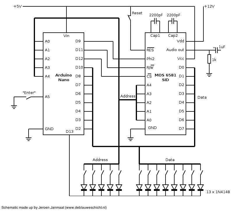
For demonstrative purposes and simplicity, all addresses, data, and control lines will be manipulated by manual switches in this realization. The remaining other necessary input - the 1 MHz clock signal, normally provided by the microprocessor - is to be generated by a microcontroller. An Arduino (in this case the Arduino Nano) features a number of counters and timers that can be used for that purpose; its internal 16 MHz clock can be devided to the required 1 MHz signal on its D9 ouput pin. Although the initial object of this project is to directly control the inputs and subsequent behavior of the SID through physical switches, the Arduino involved will also act as a latch for the switches. Incorporating a microcontroller from the start will make future addition of serial, network, or MIDI connectivity easier later on. The schematic below shows the implementation of the latching Arduino, along with the control lines and how they are connected to the SID. There are thirteen (5 address + 8 data) switches connected to A0 through A4 and D2 through D8 plus D10, respectively. The switches can be read by the microcontroller if the aforementioned pins are configured as inputs, with activated internal pull-up resistors. The software running on the Arduino monitors the state of digital input A5; when the "enter" switch is activated and A5 therefore becomes a logical 1, D13 is made "low" by the software, and the address and data switches can be read and stored. D13 is then set to 5V again and the address and data switches become ineffective. Next, all address and data pins on the Arduino are reconfigured to digital outputs, and the values that were read from the switches are copied to the outputs (the diodes in series with the switches prevent aliasing or "ghosting" during the reading phase).
CS (Chip Select) on the Arduino's digital output D12 is subsequently set to "low", which causes the SID to read the bits on its address and data buses (presently, R/W is always set to write or "low"). Finally, CS is returned to "high" and the next programming cycle can begin. A sketch that takes care of the plumbing in the Arduino can be downloaded here.
The procedure for programming the SID is now as follows:
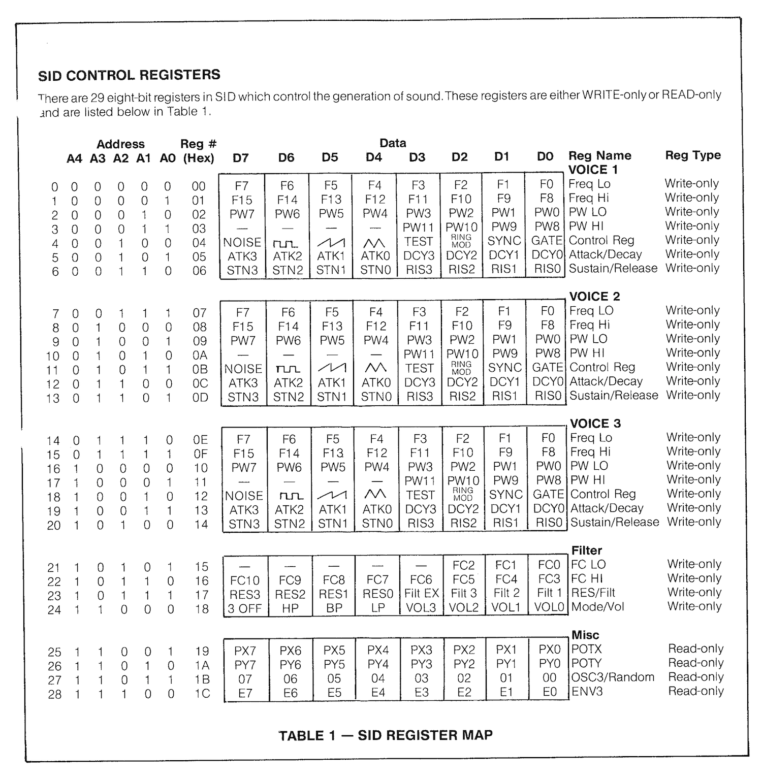
Programming SID, the slow wayOn the C64, a user can use the built-in BASIC programming language to generate music and sound effects by setting values in the SID registers using "poke" instructions. Chapter 8 in the Commodore 64 Microcomputer User Manual gives information on how to program simple melodies, and more importantly, descriptions of the various registers and how to use them. The table below (again reproduced from the datasheet) gives a concise enumeration of the controls that are at the user's disposal:
A difference between the current implementation and the C64 is that in the latter the SID is approached with a 54272 byte offset added to its register addresses. That is, the registers are mapped to a memory location starting from 54272 and ending at 54300. In this case however, no offset is present and the primitive addresses are to be used. Chapter 4 in the Commodore 64 Programmer's Reference Guide gives a convenient and short example on how to program SID to produce the sound of a bell using ring modulation:
10 S=54272 The program resets the SID chip, writes various values to the frequency and volume envelope registers, sets volume to maximum, and starts (and stops) a bell-like sound twelve times. With the register map in hand, a simpler version of the above can be input in binary on the SID using the manual switches:
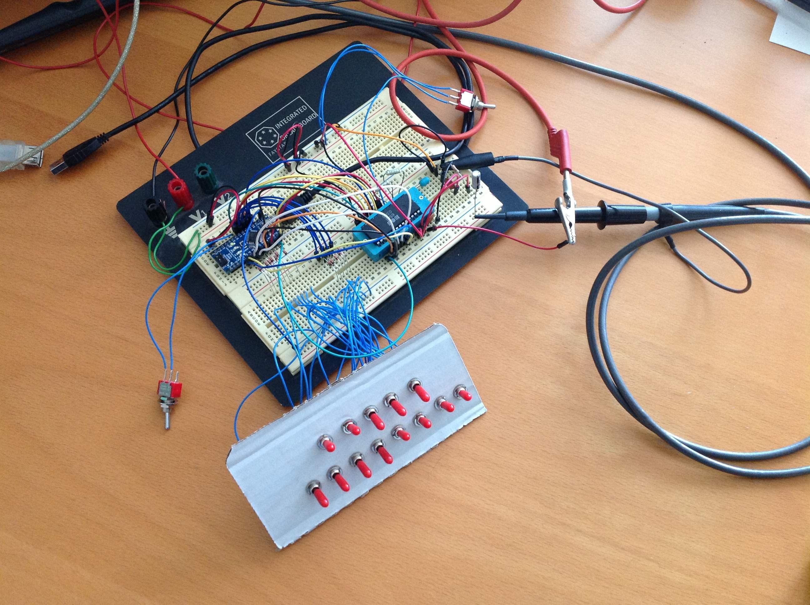
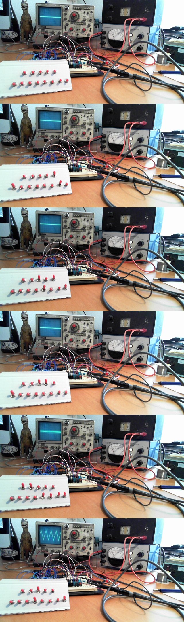
The animation below shows this sequence being entered on the binary switches. Two power supplies are used here; one providing 5 volts, the other 12 volts. The oscilloscope in the background displays the signal on the output pin of the SID chip. Note the frame marked 4/5: setting the volume to maximum results in an increased noise level, which can just be discerned on the oscilloscope screen. The switch setting seen on the final frame triggers the generation of the triangle waveform as can be seen on the display. Click on the image for the stills making up the sequence. (And oh yes, apparently the SID works!)
To doClearly it would be rather cumbersome to play melodies or elaborate sound effects in this manner. The next step therefore is to control the SID through a serial link with a computer or musical keyboard, but that will be the subject for the next article.
Credits/useful URLs
(Originally written 2013/03/11 and 2013/03/27)
|